Showing posts with label Maya. Show all posts

Wednesday, 14 December 2016

Houston We Have Another Problem

While trying to complete my animation in Maya 2016, I have never had so many issues with files and programs crashing and models messing up.

Issue #1:

Installing Maya at home.

As a student you can get Maya really easily as an installer, Just get to correct tab, select the correct OS, the version you desire and the language. At this point you can install properly using an installer. But every time I attempted to install using the installer it would always fail installing three different sections. I had even attempted getting the installer again after getting rid of the first version and trying on a different PC all together. But to no victory.


Issue #2:

Corrupted Scenes.

After creating three or four different .avi scenes ready for hand-in. I thought I would have a break and come back to it. Once I returned Maya could not recognise the file type and loaded nothing on to the scene.


Issue #3:

Corrupted Models.

Models saved as a .FBX (exported maya model) was not the correct file type and were wiped.
Models could not be exported as a .FBX later into the course.
Models saved as .MB (maya binaries) were not supported and were wiped. Meaning I had to re-texture my X-Wing model.
While trying to import my Imperial Star Destroyer and my TIE Fighter it would just change the scale of my Star Destroyed without a visible TIE-Fighter model.


Issue #4:

Corrupt .avi

We had to create our animation using .avi file format. So once I had completed one of my scenes and already previously viewed the file I had carried on creating more scenes. Later on my .avi file had been corrupted and wiped so the scene was completely lost.

Wednesday, 23 November 2016

Rigging and Skinning

Rigging and Skinning is a way to almost add a bone structure to a model and manipulating the structure so the right parts move in the correct way when adjusted.

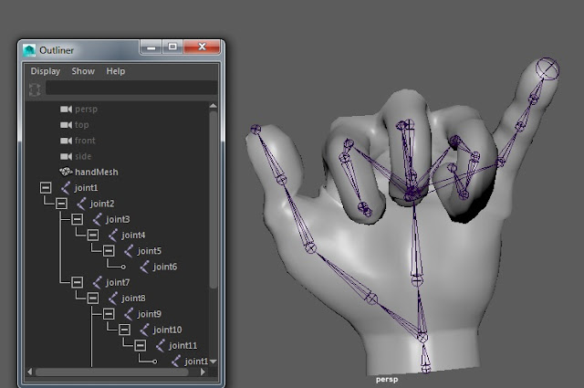
The hand below started spread without the blue wires you can see below within the hand.
To create the Rig (blue spines) got to animation mode and then Ridding>Skeleton>Create Joints Tool,
While creating the joints you may notice they are all in one flat plane. This will be because they do not know where to auto fix. So once all rigs have been created just adjust the translation to fit accordingly to how you want it. In the exercise we had to create multiple joints from a single branch. This meant using the Oueliner from the windows tab and selecting where to add an extra rig from.


Once the Rigging has been completed it is time to Skin. Like i said previously the skinning is to allow proper manipulation of the model as desired by the creator. To access this select rig and then the model and proceed to select Skin>Interactive Bind Skin.

At this point you can select different parts of the rig to see a heat map and adjust it to your liking. Your able to adjust how much the rig can be manipulated and the area .

Red = Heavily manipulated
Orange = Very manipulated
Yellow = Slightly manipulated
Green = Hardly manipulated
Blue = Not manipulated

Once completed I wanted to show my skills and make a hand with a thumbs up. Unfortunately the model hand could not support this as it is a very old example.


Wednesday, 9 November 2016

Multiple Extrudes

Extruding Multiple Faces

While creating my models I had acquired a love for the extruding tool as it made it very easy and simple to manipulate simple objects into more complicated ones. Previous to this example I was not completely sure how to create the 2 extruding faces equally. But using the connect tool between the above and below edges I could cut a perfect middle edge to separate the faces. Once I had done that I extruded a smaller face into both faces and used the vertices to make them equal. Once equal I highlighted both faces I wanted to extrude and performed the extrusion.

Tuesday, 8 November 2016

Boolean Difference Manipulation

I had realised there were 4 vents in each side piece of the Star Destroyer and wanted in semi-circular edge or cut into the object but was not sure how to do so.

My first attempt was to place a cylinder and then a cube inside of that where I would rotate the cube to cut away more than just from top to bottom but across the edge. I found this did not work at all and left straight edges inside that looked very messy.

My second attempt was to replace the cube with another cylinder so the other cut was rounded also. The end product left an almost figure '8' shape across the object and looked messy once again.

My third and final attempt was a success. Rather than using 2 object to cut, i would just manipulate the single one. By selecting a semicircle in the top face and translating it across it created the perfect effect for what i wanted to but cut out of my object.

Moving and Scaling Multiple Objects

TIE-Fighter Duplicate Wings

Initially I had just duplicated all the object required to create the wing for the purpose of having two symmetrical wings and saving the time of re-creating everything from scratch. Only issue I had from this was that all the object would rotate separately and would be muddled all over the screen rather than staying attached in the correct areas.


Above is the final example of how i had done this.

 I have gone to Windows > Outliner and selected all the objects making the one wing.

Once that was done and all objects were highlighted in the outliner I used Ctrl + G to group these objects together.

This made it so when I edited the models from the group window, all objects would be edited respectively of where they were and how they were according to its arrangement.

So I duplicated the group from the outliner and from the attribute editor I had scaled it to -1 along the x-axis. This made it so the group was rotated perfectly 180 degrees and was easily translated into its correct position.

Monday, 7 November 2016

Boolean with an Extrude


Construction of an odd shape

Before I begin I wonder what basic shape to start with. If I see a shape with a circle I will almost certainly use a cylinder or sphere as the start shape. So I had placed it correctly according to the image plane and then I noticed I wanted a flat side to be pulled up with vertices pulled closer together. So I would use a simple cube shape to cut the clean surface out and continue just as previously stated. But it needed an inner circle extruded inside itself and that took priority as there would be a face issue to extruded inwards an circle if the face was not a circle.


From the example above you can see the end result. I have given a visual example of what i had done to create the top area of the cylinder.

  1. Extrude another circular face into the cylinder.
  2. Cut a cube out of it (shown by a grey box).
  3. Extrude the upper flat surface up and transform the vertices closer together on the x-axis.
  4. Push the smaller circular face in using the extrude tool.


Friday, 4 November 2016

X-Wing Start

Cockpit

Body was created in a similar way to the TIE-Fighter wing but with extra cuts along the whole body at multiple points. Once done i created a separate object for the cock pit. This was mainly a similar way as the body with just highlighting the correct vertices and moving them to their desired location through a process of cutting around the object multiple times.
I then noticed an indent in the body of where the cockpit stand do to facilitate the cockpit i then duplicated my current cockpit and just transformed across the x-axis, this is so when i boolean difference the cockpit from body it will not cut lower than where my cockpit stands.

Wednesday, 2 November 2016

Using Multiple Image Planes

While creating the TIE-Fighter I found that the image plane I had chosen was not quite what I wanted in its detail.
There are many benefits to using multiple image planes to create your models such as finding extra detail and re-iterating what is needed to create the source you are studying. But there are drawbacks too such as you will most likely need to resize he plane vertically and horizontally, and that the image plane could be a different variation of the model. With the below example it worked well as i wanted my visual information about the center of the wing.

Wednesday, 26 October 2016

Starting the Tie-Fighter


Tie-Fighter

Upto this point I had:

 Used the rotation tool to rotate the centre sphere 90 degrees so I can easily add the cock-pit window. I had used the objects tools on the right-hand side and entered the number as 90 to make sure it was accurate.

 Used the vertex tools to adjust the first wing the correct point of the schematic.

 Cut tool around the centre of the wing and pulled the edges out to create the hexagon seen for the wing. Along with the X-ray tool to see where to translate the models and how much to edit them to the correct point.


Muti-cut tool

Trying to create the inside of the Tie-Fighter I have made many cuts in an attempt to separate the edges that go from the centre to the outside of the wing.


Saturday, 22 October 2016

Alignment tool and Grouping

Alignment Tool

Using a simple technique you can easily translate items into a position where they fix around another item. In this example below you can see a cylinder, circular pyramid, sphere and cube sitting all on top of one another. If I attempted this without the alignment tool there is a high possibility that the object would collide with each other: but since I used the tool i know they they do not collide yet still touch.


Grouping


Previously I have created many images in photoshop and animations on flash 8, so I understand the significance of using the grouping tool. Allowing me to store cylinders in lists together keeps the screen tidy but also allows me to keep models together for sorting out what I am editing together whether it is translating or re-sizing.

Friday, 21 October 2016

F-16 Plane

This is the first model of a ship i had made. There are ways I could improve but for a beginner model I am very pleased.
Isues:


  • The body of the plane goes into the cockpit. I could use the boolean tool to get rid of a certain chunk so it is no longer visible. 
  • The alignment of the image planes were not perfect so I would often refer to 2 image as the final sizing and scaling but use the other for scaling where it was not possible on the others. 
  • Visible polygons on the nose.
Improvements:


  • Using and highlighting the correct vertices for perfect manipulation.
  • Use of the extrude tool for the back engine. 
  • Knowing what shapes to use in what areas and how to cut an image with the Ctrl key. 

Ship steering wheel

Final Product.

Creating this i learnt techniques such as:

Cutting equally around a cylinder.
Excelling at the extruding tool. Extrude by rotation, enlarging.
Creating the disc for the middle by creative creation.
Deburring for smooth edges (ergonomically).

Wednesday, 5 October 2016

My First Maya Model

Following the tutorial posted on the VLE I have created a simple house.
In this tutorial I learnt everything I have so far on this program, such as:

  • Moving the camera around the model.
  • Creating new faces.
  • Extruding and Intruding faces.
  • Adding Divisions.

I have not got much confidence with this program but it is early days into using it.

Here is the end product of what I have created so far (05.10.16, 11:50).


              We were told it should now be easier to add doors and more windows so I have added the two extra windows on the left side compared to the tutorial. But now I am going to try adding door between the windows.